The serial port sometimes looks like a tangle of wires that is hard to understand. In this brief tutorial, we will try to explain it in simple and understandable terms with the help of some images that won't make things too complicated.
In embedded world, connecting circuits, whether they are processors or other integrated circuits, is essential to create a cohesive system. For these circuits to communicate and exchange information, they need to use a common communication protocol. There are many communication protocols designed for this purpose, and they generally fall into two main categories: parallel and serial.
Consider the two types of interfaces as different kinds of roads: a parallel interface resembles an 8-lane expressway, while a serial interface is more like a narrow country lane. Over a given period, the expressway can move more cars to their destinations, but the country lane gets the job done and is much cheaper to build.
Parallel communication has notable advantages. It's quick, direct, and relatively easy to implement, but it requires a large number of input/output (I/O) lines. If you've ever upgraded a project from an Arduino Uno to a Mega, you're aware of how limited and valuable those I/O lines can be. Consequently, we often choose serial communication, giving up potential speed to conserve pin usage.

A serial interface, transmitting one bit every clock pulse.
Many serial protocols have been designed over the years to meet specific requirements of embedded systems. Well-known examples include USB (universal serial bus) and Ethernet. Other frequently used serial interfaces are SPI, I2C, that are not part of this tutorial. These serial interfaces can be categorized as either synchronous or asynchronous.
Synchronous serial interface
A synchronous serial interface uses a clock signal alongside its data line(s), ensuring all devices on a synchronous bus share a common clock. This setup facilitates simpler and often faster data transfers but requires at least one extra wire between the devices. Examples of synchronous interfaces include SPI and I²C (I2C).
On the other hand, asynchronous communication transfers data without an external clock signal. This method is perfect for reducing the number of required wires and I/O pins, though it demands more effort to ensure reliable data transmission and reception. The protocol we'll discuss in this tutorial is the most common form of asynchronous communication. It's so prevalent that when people refer to “serial,” they typically mean this protocol (as you'll see throughout this tutorial).
The serial protocol we'll cover is extensively used in embedded electronics. If you're integrating devices like GPS modules, Bluetooth, XBee's, serial LCDs, or various other peripherals into your project, you'll need to employ some serial communication skills.
Asynchronous serial interface.
The asynchronous serial protocol includes several built-in rules that ensure reliable and error-free data transmission. These mechanisms, which come into play because we aren't using an external clock signal, include:
- Data bits
- Synchronization bits
- Parity bits
- Baud rate
These various signaling mechanisms mean there isn't just one way to send data serially. The protocol is highly flexible, but it's crucial that both devices on a serial bus are configured to use the same settings.
Baud Rate
The baud rate defines the speed at which data is transmitted over a serial line, usually measured in bits per second (bps). By inverting the baud rate, you can determine the time it takes to send a single bit. This rate dictates how long the transmitter holds a line high or low and the interval at which the receiver samples the line.
Baud rates can vary widely, but both devices must operate at the same rate. Common baud rates include 9600 bps for simple tasks where speed isn't critical, along with other standard rates such as 1200, 2400, 4800, 19200, 38400, 57600, and 115200 bps.
Higher baud rates allow faster data transmission, but there are practical limits. Speeds above 115200 bps are uncommon because they can lead to errors as clocks and sampling periods struggle to keep up.
Framing the Data
Each data block, usually a byte, is sent as a packet or frame of bits. Frames are created by adding synchronization and parity bits to the data.
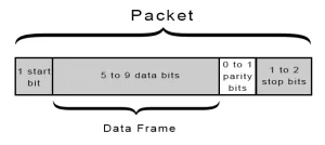
A Serial Packet
Data Chunk
The core of every serial packet is the data it carries. This block of data, called a chunk, can range from 5 to 9 bits in size. The standard size is 8 bits, but other sizes can be useful; for example, a 7-bit data chunk is more efficient for transferring 7-bit ASCII characters.
Both devices must agree on the data length and the order of bits (endianness). Data is typically transferred least-significant bit (LSB) first unless otherwise specified.
Synchronization Bits
Synchronization bits include the start bit and the stop bit(s), which mark the beginning and end of a data packet. There is always one start bit, while the number of stop bits can be one or two, but is usually set to one.
The start bit transitions from an idle state (1) to active (0), while stop bits return the line to idle (1).
Parity Bits
Parity bits provide a basic level of error checking. There are two types: odd and even. The parity bit is set based on the sum of the data bits. For example, if the data byte 0b01011101 has an odd number of 1's (five), an even parity bit would be 1. If using odd parity, the bit would be 0.
Parity bits are optional and not commonly used. They help in noisy environments but slow down data transfer and require error-handling mechanisms to resend failed data.
9600 8N1 Example
The 9600 8N1 protocol (9600 baud, 8 data bits, no parity, 1 stop bit) is commonly used. For instance, transmitting the ASCII characters 'O' and 'K' involves creating two data packets. The ASCII value of 'O' (uppercase) is 79, which is 01001111 in binary, and 'K' is 01001011 in binary. Sync bits are added to these values.
Data is generally transferred LSB first. Each byte involves 10 bits: one start bit, 8 data bits, and one stop bit. At 9600 bps, each bit is held for 104 microseconds.
Knowing how to construct serial packets is essential before moving on to the hardware section, where we'll see how the 1's, 0's, and baud rate are implemented at the signal level.