Serial Port ModBus Serial and TCP
ModBus Serial RTU/ASCII and TCP
The Modbus protocol is a robust and widely-used communication protocol specifically designed for industrial automation systems. Developed in 1979 by Modicon (now Schneider Electric), Modbus has become the de facto standard for connecting industrial electronic devices. It is an open protocol, meaning it is royalty-free and widely adopted in the industry. Modbus allows for communication between multiple devices connected to the same network, such as a system that measures temperature and humidity and communicates the results to a computer.
Modbus ASCII
Modbus ASCII (American Standard Code for Information Interchange) is a version of the protocol where messages are encoded in ASCII characters. Each byte in a message is sent as two ASCII characters. This format is human-readable and easy to debug. The ASCII mode is generally used over serial communication lines such as RS-232 or RS-485.
- Start/Stop Bits: Each message starts with a colon (':') character and ends with a carriage return-line feed (CRLF) sequence.
- Frame Format: Messages contain a device address, function code, data, and a checksum.
- Checksum: The checksum is a Longitudinal Redundancy Check (LRC) which ensures data integrity.
- Usage: ASCII mode is slower than RTU mode because it uses more characters to send the same information, but it is easier to interpret and debug manually.
Modbus RTU
Modbus RTU (Remote Terminal Unit) is a more compact and efficient version of the protocol compared to Modbus ASCII. In RTU mode, messages are encoded in binary format, making them smaller and faster to transmit than ASCII messages. This mode is also typically used over serial communication lines such as RS-232 or RS-485.
- Start/Stop Bits: Messages are framed by idle periods, with a 3.5 character time interval of silence indicating the end of a message and the beginning of a new one.
- Frame Format: RTU messages contain a device address, function code, data, and a Cyclic Redundancy Check (CRC).
- Checksum: The CRC is a more robust error-checking method than the LRC used in ASCII mode.
- Usage: RTU mode is preferred in industrial settings due to its efficiency and faster communication speeds.
Modbus TCP
Modbus TCP (Transmission Control Protocol) is a version of the Modbus protocol designed for Ethernet networks. This version encapsulates Modbus RTU messages within TCP/IP packets, allowing for communication over long distances and integration with modern network infrastructures.
- Frame Format: The Modbus TCP frame contains an additional header, known as the Modbus Application Protocol (MBAP) header, which includes information such as a transaction identifier, protocol identifier, length field, and unit identifier.
- Transport Protocol: Uses standard TCP/IP for transport, enabling reliable and connection-oriented communication.
- Usage: Modbus TCP is ideal for applications requiring integration with IP-based networks, such as factory automation systems, SCADA (Supervisory Control and Data Acquisition) systems, and other Ethernet-based industrial devices.
SerialTool supports the Modbus protocol, making the software even more comprehensive. As stated on the official SerialTool page dedicated to Modbus, the tool utilizes the stable and open-source library LibModbus (https://libmodbus.org/).
SerialTool supports the previously described modes for transmitting the Modbus protocol via serial communication.
First, you'll need a slave device capable of responding to commands from SerialTool. There are a few software options available that allow you to test Modbus in slave mode, but these are not free, so I won't mention them here. Ideally, you should have the actual device you intend to test.
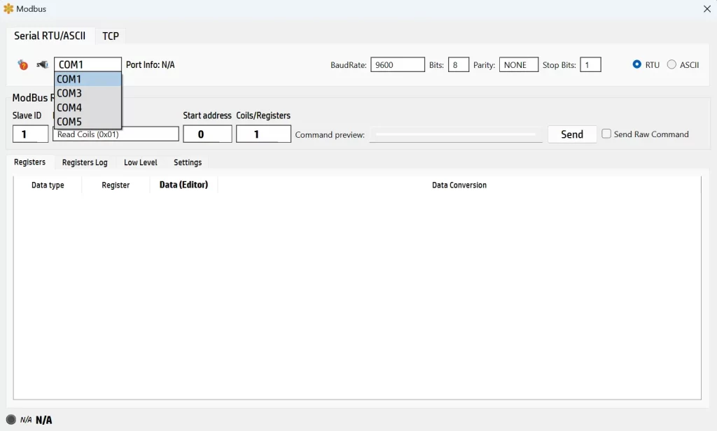
SerialTool ModBus Serial Port Configuration
This screenshot showcases the Modbus configuration interface within SerialTool, specifically designed for setting up and managing Modbus communications. Here, you can configure your connection for either Modbus RTU/ASCII or Modbus TCP, making it versatile for various industrial communication needs.
Before diving into the details, it’s important to note a crucial step: ensure that any serial ports you intend to use for Modbus are not currently opened in the main SerialTool interface. If a port is already in use there, this Modbus module will detect it as busy and won’t be able to function correctly. Simply CLOSE the port from the main SerialTool configuration to avoid this issue.
Now, onto the setup. The interface lets you select the desired COM port from a dropdown menu, ensuring you're connected to the right device. You can configure key settings like baud rate, data bits, parity, and stop bits to match the specifications of your Modbus device. Switching between RTU and ASCII modes is straightforward, giving you the flexibility to adapt to different communication protocols seamlessly. Remember that you need to configure RTU or ASCII depending on how your remote device is capable of receiving the data. This is a very important parameter!
For example, to read coils from a slave device, you simply specify the slave ID, the starting address, and the number of coils or registers you wish to interact with. The command preview updates in real-time, providing a clear view of the Modbus command being sent.
This user-friendly design ensures that even those new to Modbus can get up and running quickly, while more experienced users will appreciate the detailed control and feedback provided by the interface.
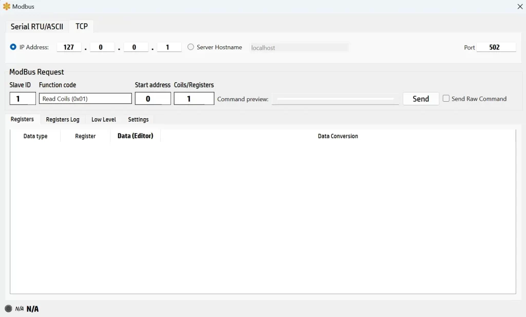
SerialTool ModBus TCP Configuration
This imageshows the Modbus configuration interface within SerialTool, specifically set to handle Modbus TCP communications. It’s a straightforward setup that makes configuring your Modbus TCP connection a piece of cake.
At the top, you can see the option to enter the IP address or the server hostname of the device you want to communicate with. In this example, the IP address is set to 127.0.0.1, which is commonly used for local testing on the same machine. Next to the IP address field, you can specify the port number, which is set to 502 by default for Modbus TCP communication.
Below that, the Modbus Request section lets you configure the details of the Modbus command you want to send, and we will get into those details in the next paragraph.
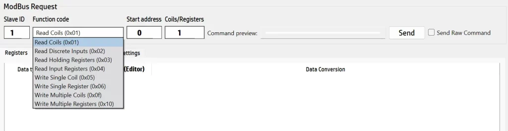
This image displays the Modbus Request configuration interface within SerialTool, specifically highlighting the selection of Modbus function codes. This interface is designed to allow users to construct and send Modbus commands to a slave device, facilitating the testing and management of Modbus communications.
Overview of Modbus Commands
1. Read Coils (0x01):
- Description: This command reads the status of coils (binary outputs) from the slave device. Coils are typically used to represent digital outputs such as relays or switches.
- Usage: You specify the starting address and the number of coils to read. The slave responds with the status of the requested coils (ON or OFF).
2. Read Discrete Inputs (0x02):
- Description: This command reads the status of discrete inputs (binary inputs) from the slave device. Discrete inputs usually represent digital inputs like sensor states.
- Usage: Similar to reading coils, you provide the starting address and the number of inputs to read. The slave returns the status of the requested inputs.
3. Read Holding Registers (0x03):
- Description: This command reads the contents of holding registers, which are used to store general data that the master device needs to read, such as setpoints or configuration parameters.
- Usage: You define the starting address and the number of registers to read. The slave device responds with the values of the requested registers.
4. Read Input Registers (0x04):
- Description: This command reads the contents of input registers, which are typically used to store read-only data such as measurements from sensors.
- Usage: You specify the starting address and the number of input registers to read. The slave returns the values of the requested registers.
5. Write Single Coil (0x05):
- Description: This command writes a single coil to either ON or OFF state. It's used to control binary outputs like relays or switches on the slave device.
- Usage: You provide the address of the coil and the desired state (ON or OFF). The slave device updates the coil status accordingly.
6. Write Single Register (0x06):
- Description: This command writes a value to a single holding register. It's commonly used to set parameters or control outputs in the slave device.
- Usage: You specify the address of the register and the value to write. The slave updates the register with the new value.
7. Write Multiple Coils (0x0F):
- Description: This command writes multiple coils in one operation, setting several binary outputs simultaneously.
- Usage: You define the starting address and provide the status for each coil in the sequence. The slave updates the coils accordingly.
8. Write Multiple Registers (0x10):
- Description: This command writes values to multiple holding registers in one operation, allowing for batch updates of parameters or control settings.
- Usage: You specify the starting address and the values to write to the registers. The slave updates the registers with the provided values.
Using the Interface
In the interface, you start by selecting the desired function code from a dropdown menu, which includes the commands listed above. You then enter the slave ID, the starting address, and the number of coils or registers involved in the command. The “Command preview” shows the constructed command, and you can send the command by clicking the “Send” button. If you need to send a raw command, there's an option to enable that as well.
This setup allows for precise control and testing of Modbus devices, making it easier to configure and debug Modbus communications in industrial environments.
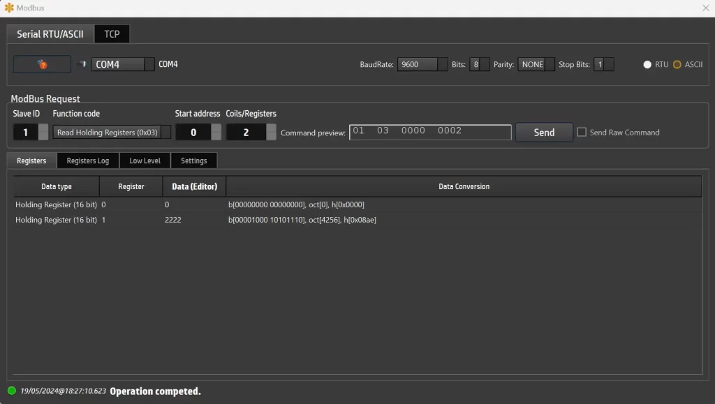
ModBus: Read Holding Registers 0x03 example
I switched to the black and yellow screen appearance of SerialTool because the blue and white style does not show the Command Preview properly in version 1.8.0 of SerialTool (they may need to fix this issue).
This screenshot is showcasing a Modbus RTU request using the “Read Holding Registers” command (function code 0x03). This command is used to read the contents of holding registers, which are often used for storing general data that the master device needs to retrieve.
Breakdown of the Modbus Read Command (0x03)
-
Configuration Settings:
- The interface is set to use COM4 as the communication port, configured with a baud rate of 9600, 8 data bits, no parity, and 1 stop bit. The RTU mode is selected for communication.
-
Modbus Request Details:
- Slave ID: 1
- This identifies the specific slave device on the Modbus network to which the request is directed.
- Function Code: Read Holding Registers (0x03)
- This function code instructs the slave device to read the values stored in its holding registers.
- Start Address: 0
- The starting address in the slave's memory from which the data reading will begin.
- Number of Registers: 2
- The number of consecutive holding registers to read, starting from the specified start address.
-
Command Preview:
- The command preview field shows the complete Modbus request in hexadecimal format:
01 03 0000 0002. This breakdown is as follows:
01: Slave ID03: Function code for reading holding registers0000: Starting address0002: Number of registers to read
-
Response Data:
- After sending the request, the response data is displayed in the Registers tab. The Data Editor shows the contents of the requested registers.
- Register 0: Contains the value
0 (binary 00000000 00000000, octal 0, hexadecimal 0x0000).
- Register 1: Contains the value
2222 (binary 00001000 10101110, octal 4256, hexadecimal 0x08ae).
-
Interface Tabs:
- Below the Modbus Request section, there are tabs for Registers, Registers Log, Low Level, and Settings. These tabs provide additional functionalities for logging register changes, accessing low-level communication details, and adjusting various settings.
-
Operation Status:
- At the bottom of the screen, a status message indicates that the operation has been completed successfully, with a timestamp for reference.
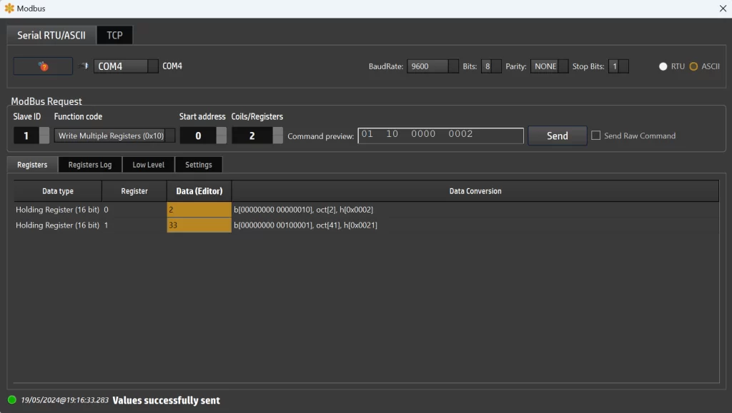
ModBus: Write Multiple Registers 0x10 example
This screenshot illustrates the process of writing multiple registers via Modbus using SerialTool.
Writing Multiple Registers with Modbus Function Code 0x10
-
Configuration Settings:
- The interface is set to use COM4 as the communication port, configured with a baud rate of 9600, 8 data bits, no parity, and 1 stop bit. RTU mode is selected for communication.
-
Modbus Request Details:
- Slave ID: 1
- This identifies the specific slave device on the Modbus network to which the command is directed.
- Function Code: Write Multiple Registers (0x10)
- This function code is used to write values to multiple holding registers on the slave device.
- Start Address: 0
- The starting address in the slave's memory where the writing will begin.
- Number of Registers: 2
- The number of consecutive holding registers to write, starting from the specified start address.
-
Command Preview:
- The command preview field shows the complete Modbus request in hexadecimal format:
01 10 0000 0002. This breakdown is as follows:
01: Slave ID10: Function code for writing multiple registers0000: Starting address0002: Number of registers to write
Steps to Write Multiple Registers
-
Read the Registers:
- Initially, the registers must be read to understand their current state. This can be done using a read command (function code 0x03). The values of the registers will be displayed in the Data Editor.
-
Edit Register Values:
- Once the current values are displayed, you can edit the content directly in the yellow-marked cells within the Data Editor. In this example, the values to be written are:
- Register 0: New value is
2
- Register 1: New value is
33
-
Send the Write Command:
- After editing the values, press the “Send” button to transmit the new values to the remote device. The interface confirms the command by updating the command preview and sending the data.
-
Verify the Operation:
- At the bottom of the screen, a status message confirms that the values were successfully sent, along with a timestamp for reference. This indicates that the operation completed without errors.
Data Conversion:
- The Data Editor also shows binary, octal, and hexadecimal representations of the values:
- For Register 0:
- Binary:
00000000 00000010
- Octal:
2
- Hexadecimal:
0x0002
- For Register 1:
- Binary:
00000000 00100001
- Octal:
41
- Hexadecimal:
0x0021
This interface in SerialTool makes it easy to write multiple registers to a Modbus device. By first reading the registers and then editing the values in the yellow-marked cells, users can update the device's settings accurately. The intuitive command preview and real-time feedback ensure that the process is straightforward and reliable, making SerialTool a powerful tool for managing Modbus communications.